

Catalog
Specifications
|
Maximum Recovery
|
Dimensions
|
4" Vent Pipe
|
6" Vent Pipe
|
General Information
|
Features
|
Other Features
|
Testing and Certifications
|
Warranty
|
Note
Specifications
Manufacturer |
N/A State® |
Standard Type |
N/A ASME |
Input Power |
N/A 300000 BTU/hr88 kW |
Thermal Efficiency |
N/A 96 % |
Capacity |
N/A 130 U.S. gal497 L |
Standard Approximate Shipping Weight |
N/A 855 lb408 kg |
ASME Approximate Shipping Weight |
N/A 855 lb408 kg |
Minimum Supply Natural Gas Line Size (N.P.T.) |
N/A 1-1/4 in |
Minimum Supply Propane Gas Line Size (N.P.T.) |
N/A 1-1/4 in |
Water Connection |
N/A 1-1/2 in |
Type |
N/A Liquid Propane Gas Natural Gas |
Style |
N/A Ultra Force™ |
Size |
N/A C |
Industry Standards |
N/A AHRI Certified® ASHRAE/IESNA 90.1 ASME Certified CSA® Certified Energy Star UL® Listed |
Maximum Recovery
Recovery at 30 ºF Temperature Rise |
N/A 1164 gal/h |
Recovery at 17 ºC Temperature Rise |
N/A 4406 L/h |
Recovery at 40 ºF Temperature Rise |
N/A 873 gal/h |
Recovery at 22 ºC Temperature Rise |
N/A 3304 L/h |
Recovery at 50 ºF Temperature Rise |
N/A 699 gal/h |
Recovery at 28 ºC Temperature Rise |
N/A 2644 L/h |
Recovery at 60 ºF Temperature Rise |
N/A 582 gal/h |
Recovery at 33 ºC Temperature Rise |
N/A 2203 L/h |
Recovery at 70 ºF Temperature Rise |
N/A 499 gal/h |
Recovery at 39 ºC Temperature Rise |
N/A 1888 L/h |
Recovery at 80 ºF Temperature Rise |
N/A 436 gal/h |
Recovery at 44 ºC Temperature Rise |
N/A 1652 L/h |
Recovery at 90 ºF Temperature Rise |
N/A 388 gal/h |
Recovery at 50 ºC Temperature Rise |
N/A 1469 L/h |
Recovery at 100 ºF Temperature Rise |
N/A 349 gal/h |
Recovery at 56 ºC Temperature Rise |
N/A 1322 L/h |
Recovery at 110 ºF Temperature Rise |
N/A 318 gal/h |
Recovery at 61 ºC Temperature Rise |
N/A 1201 L/h |
Recovery at 120 ºF Temperature Rise |
N/A 291 gal/h |
Recovery at 67 ºC Temperature Rise |
N/A 1102 L/h |
Recovery at 130 ºF Temperature Rise |
N/A 269 gal/h |
Recovery at 72 ºC Temperature Rise |
N/A 1017 L/h |
Recovery at 140 ºF Temperature Rise |
N/A 250 gal/h |
Recovery at 78 ºC Temperature Rise |
N/A 945 L/h |
Dimensions
Schematic |
N/A
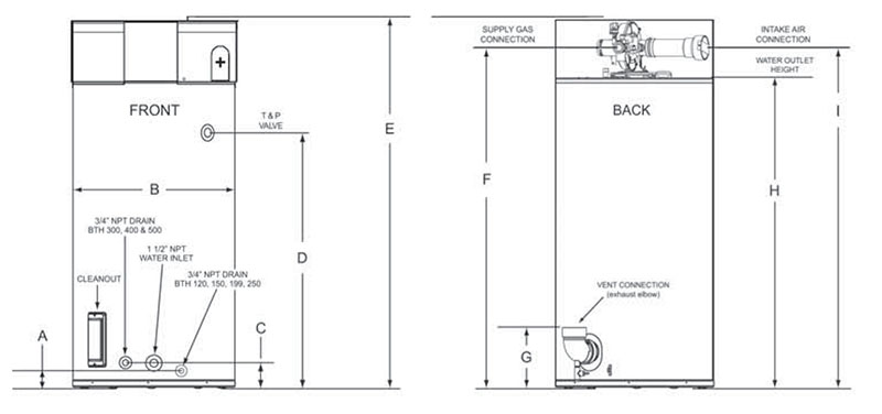 |
Dimension A |
N/A 4.86 in12.34 cm |
Dimension B |
N/A 33.12 in84.1 cm |
Dimension C |
N/A 4.86 in12.34 cm |
Dimension D |
N/A 50.77 in129 cm |
Dimension E |
N/A 75.5 in191.8 cm |
Dimension F |
N/A 69 in175.3 cm |
Dimension G |
N/A 12 in30.5 cm |
Dimension H |
N/A 63 in160 cm |
Dimension I |
N/A 69 in175.3 cm |
4" Vent Pipe
One 90º Elbows for Maximum 4" Vent Pipe |
N/A 65 ft19.8 m |
Two 90º Elbows for Maximum 4" Vent Pipe |
N/A 60 ft18.2 m |
Three 90º Elbows for Maximum 4" Vent Pipe |
N/A 55 ft16.8 m |
Four 90º Elbows for Maximum 4" Vent Pipe |
N/A 50 ft15.2 m |
Five 90º Elbows for Maximum 4" Vent Pipe |
N/A 45 ft13.7 m |
Six 90º Elbows for Maximum 4" Vent Pipe |
N/A 40 ft12.2 m |
6" Vent Pipe
One 90º Elbows for Maximum 6" Vent Pipe |
N/A 115 ft35 m |
Two 90º Elbows for Maximum 6" Vent Pipe |
N/A 110 ft33.5 m |
Three 90º Elbows for Maximum 6" Vent Pipe |
N/A 105 ft32 m |
Four 90º Elbows for Maximum 6" Vent Pipe |
N/A 100 ft30.5 m |
Five 90º Elbows for Maximum 6" Vent Pipe |
N/A 95 ft29 m |
Six 90º Elbows for Maximum 6" Vent Pipe |
N/A 90 ft27.4 m |
General Information
General Information |
N/A
Installation Considerations
|
Features
Features |
N/A
Down-Fired Low NOx Power Burner Design
|
Other Features
Other Features |
N/A
Commercial Grade Glasslined Tank & Heat Exchanger for Long-Term Protection Against Corrosion
|
Testing and Certifications
Testing and Certifications |
N/A
ASME Construction
CSA® Certified and ASME Rated T&P Relief Valve All models are ENERGY STAR® Qualified |
Note
Note |
N/A
Recovery capacities are based on heater performance at 95% and 96% thermal efficiency. Add "A" to model number when ordering ASME. Optional on all Models. Maximum gas supply pressure: 10" W.C. natural gas 13" W.C. propane. Electrical requirements: 120/60 Hz VAC, Blower 2.2 Amps FL, Igniter 4.0 Amps. Minimum clearance to remove top cover. Additional clearances recommended in case service is needed. Maximum number of 90º elbows allowed for the vent (exhaust) pipe is six (6). Maximum number of 90º elbows allowed on the intake air pipe is six (6). Two (2) 45º elbows equal one (1) 90º elbow. Center line of water outlet on top of the water heaters is approximately 7 inches from the front edge of the water heater. |